High-precision Current Testing
Hioki's clamp type AC/DC current sensors can be connected directly to Hioki Power Analyzers and Memory HiCorders.
Also, it can be connected to Power Meters, Oscilloscopes, DMMs, etc. by using an optional sensor unit.
Clamp-style current sensors can be affixed without cutting the line under measurement. Thanks to that design, they can measure current in applications where it’s not possible to cut lines, including testing of EVs on chassis dynamometers and evaluation of operational solar power systems.

The CT6840A series can measure current in operating vehicles since there’s no need to cut cables. Combined with a power analyzer, these instruments can accurately integrate current and power during charging and discharging of system batteries in order to make WLTP-compliant fuel efficiency measurements.
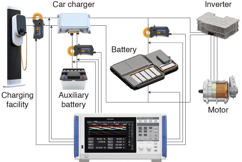
While clamp-style current sensors are generally praised for their convenience, they usually pose disadvantages in terms of measurement precision. However, the CT6840A series delivers unparalleled measurement precision in a clamp-style design, allowing accurate measurement of DC power in battery-powered EVs and solar power systems.
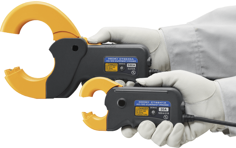
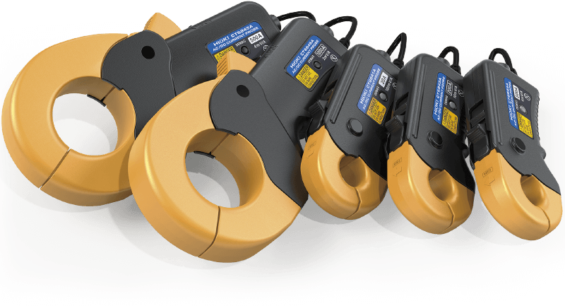
Rated current/Frequency band/Diameter of measurable conductors
CT6841A: 20 A/DC to 2 MHz/φ20 mm or less
CT6843A: 200 A/DC to 700 kHz/φ20 mm or less
CT6844A: 500 A/DC to 500 kHz/φ20 mm or less
CT6845A: 500 A/DC to 200 kHz/φ50 mm or less
CT6846A: 1000 A/DC to 100 kHz/φ50 mm or less
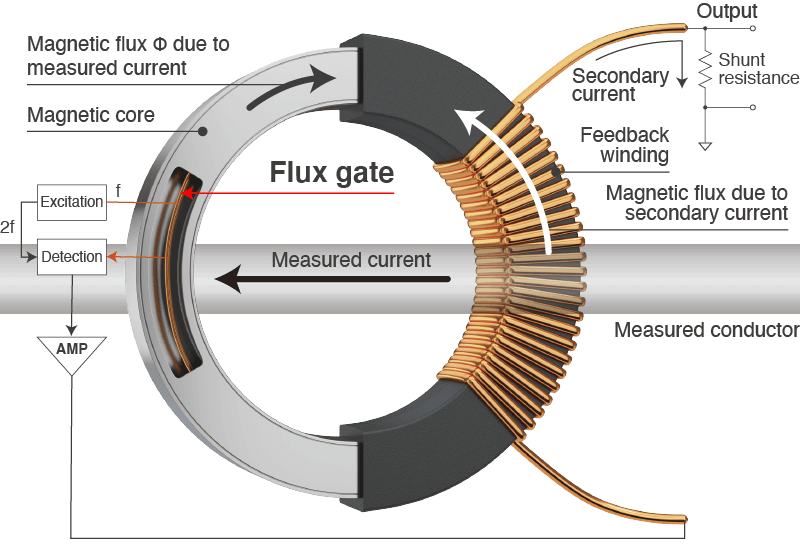
Temperature characteristics are an issue for current sensors that can manage DC current. The CT6840A series uses the flux gate detection method. Unlike the standard Hall element detection method, the flux gate method is more resistant to temperature variations, allowing instruments to accurately measure current in a variety of test environments.
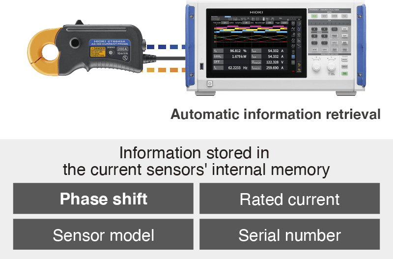
The CT6840A series provides automatic phase correction for automatically correcting current sensor phase just by connecting to the Power Analyzer PW8001. This function automates configuration of phase correction values, a process that previously had to be carried out manually, eliminating settings errors and facilitating accurate power measurement. (All current sensors have phase characteristics, and the Power Analyzer performs phase correction so that power can be measured accurately.)
| Rated current | 500 A AC/DC |
|---|---|
| Frequency bandwidth | DC to 500 kHz |
| Diameter of measurable conductors | Max. φ 20 mm (0.79 in.) |
| Max. allowable input | ±800 A peak (Within 20 ms in an environment of 40°C/104°F or less) |
| Output voltage | 4 mV/A |
| Output resistance | 50 Ω ± 10 Ω |
| Accuracy (amplitude) ±(% of reading + % of full scale) |
DC: 0.2% + 0.02% DC < f ≤ 100 Hz: 0.2% + 0.01% |
| Linearity | ±20 ppm Typical |
| Common-Mode Voltage Rejection Ratio (CMRR) |
DC to 1 kHz:150 dB or greater 1 kHz to 10kHz:135 dB or greater 10 kHz to 100 kHz:120 dB or greater 100 kHz to 300 kHz:100 dB or greater (effect on output voltage and common mode voltage) |
| Automatic phase correction | Automatically performs phase correction when connected to PW8001 |
| Operating temperature, humidity | -40°C to 85°C (-40°F to 185°F), 80% RH or less |
| Standards | Safety IEC 61010 Type D EMC IEC 61326 |
| Withstand voltage | AC 4260 V |
| Power supply | Power suppled via the Power Analyzer PW8001, PW6001, PW3390, Sensor Unit CT9555, CT9556, CT9557, or 3CH CURRENT UNIT U8977 |
| Max. rated power | 7 VA or less (When measuring 500 A/55 Hz with ±12 V power supply) |
| Dimensions and mass | Approx. 153 mm W × 67 mm H × 25 mm D (approx. 6.02 in. W × 2.64 in. H × 0.98 in. D), 400 g (14.1 oz.) |
| Cable length | Approx. 3 m (9.84 ft.) |
| Included accessories | Markup bands ×6, Carrying Case, Instruction Manual |