Fluke 1770 Series Three-Phase Power Quality Analyzers eliminate the complexities of power quality logging, troubleshooting, and analysis. Engineered to be the faster, easier way to perform power quality studies, the 1770 Series offers automatic measurements, a straightforward user interface and setup, best-in-class specifications, and a simplified reporting platform. The instrument can also be powered directly from the measurement circuit, eliminating the need to find a power outlet or use a lengthy extension cord
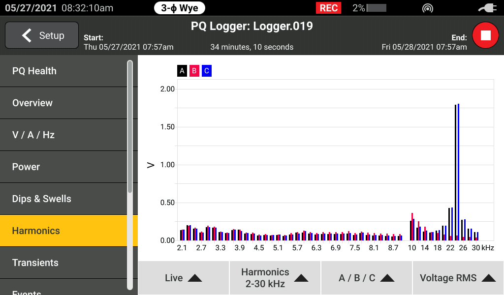
With the 1770 Series you’ll never miss a critical power quality event—from fast transients up to 8 kV, harmonics up to 30 kHz, dips and swells, as well as the voltage, current, and power measurements that enable you to characterize your electrical system.
Whether you’re performing a quick system check or a detailed power quality study, consistent data is key. The Fluke 1770 Series offers a unique automatic measurement capture system that helps ensure you’re collecting the right data every time, while still giving you the flexibility to select and adjust specific parameters as needed. More than 500 power quality parameters are captured by default and the guided setup makes it easy to select the right parameters for the system you’re working on. Logged data is instantly viewable, downloadable, and shareable with Fluke Energy Analyze Plus software so you never need to wait to finish a session before reviewing results or analyzing data.
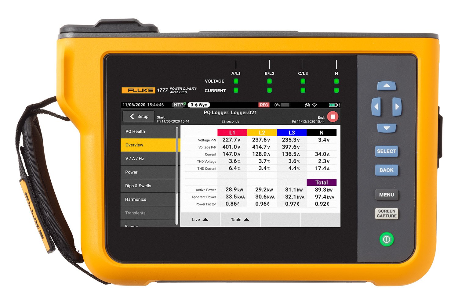
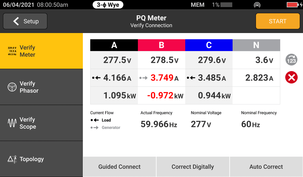
The Fluke 1770 Series are 2-in-1 devices that combine the troubleshooting functionality of a power quality meter with the robust analysis and logging capabilities of a standalone power quality analyzer—in a single, easy-to-use, handheld device.
The ‘PQ Meter’ function gives you immediate access to live onscreen data in the field so you can quickly identify potential problems while troubleshooting. The detailed ‘PQ Logging and Analysis’ function eliminates the complexity of performing power quality studies by guiding you through the setup process ensuring you’re capturing the right data every time. Couple these measurement modes with a unique measurement connection autocorrect function and you can be confident that you never need to worry about going back for a second measurement—even if you were unsure about what to look for when you started.
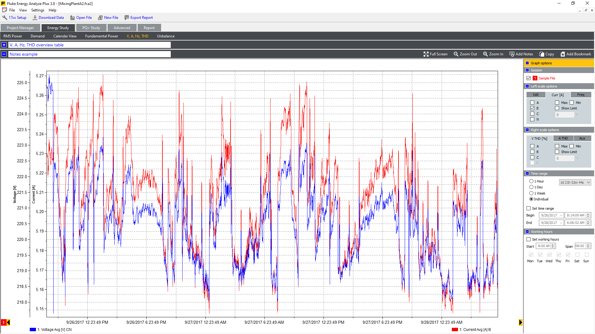
Fluke 1770 Series Power Quality Analyzers come standard with the powerful Fluke Energy Analyze Plus software, designed to eliminate the hassles found with other multi-purpose application software. Energy Analyze Plus helps you evaluate power quality data right out of the box and without extensive training.
Energy Analyze Plus makes downloading, analyzing, tracking, and reporting power quality and energy data easier than ever. Quickly compare results to historical values, benchmark against industry norms, compare measured data to local conditions, and create a more complete picture of what’s occurring across your facility, even as the data is still being collected. Energy Analyze Plus offers unified support for the Fluke 1730, 1740, and 1770 Series of Energy Loggers and Power Quality Analyzers.
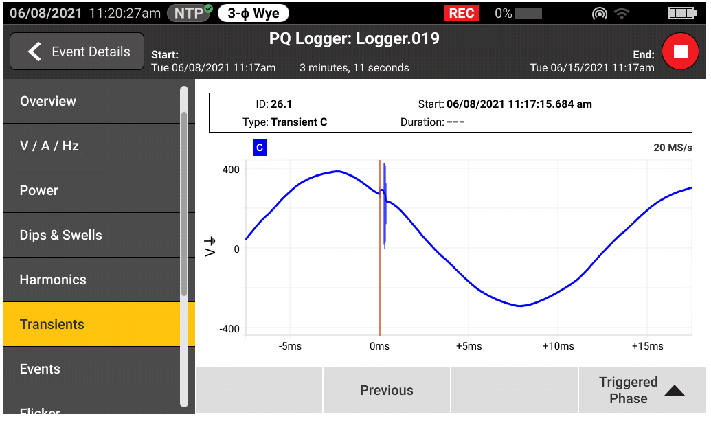
Transients negatively impact otherwise healthy systems every day and their potential to damage your equipment can’t be underestimated. Whether your system is experiencing impulsive or oscillatory transients, the results can be devastating and cause problems ranging from insulation failures to total equipment failures. The Fluke 1775 and Fluke 1777 incorporate advanced transient capture technology to help you clearly identify high-speed voltage transients, so you have the data you need to stop them in their tracks. The Fluke 1775 Power Quality Analyzer has 1MHz sampling capability to capture fast transients, while the Fluke 1777 Power Quality Analyzer has 20MHz sampling capability to capture the fastest transients in high detail.
The Fluke 1770 Series was designed to be safe and easy to use in any measurement environ¬ment. The 1770 Series allows you to capture a full range of power quality variables as well as high-speed waveforms, high-speed transients, and higher frequency harmonics, all of which are instantly viewable on the large, high-resolution screen. With a best-in-class CAT IV 600 V / CAT III 1000 V overvoltage rating, these analyzers can be used at the service entrance or downstream, measuring AC and DC inputs, and harmonics measuring up to 30 kHz. With the 1770 Series you can be confident that you’ll capture the data you need to make better maintenance decisions no matter the task.
| Applications | 1773 | 1775 | 1777 |
|---|---|---|---|
| Energy surveys and load testing | ✔ | ✔ | ✔ |
| Harmonic surveys | ✔ | ✔ | ✔ |
| Nuisance circuit breaker tripping | ✔ | ✔ | |
| Electric utility power quality surveys | ✔ | ✔ | |
| Discovery of equipment failures caused by 8kV microsecond transients | ✔ | ✔ | |
| Discovery of equipment failures caused by 8kV nanosecond transients | ✔ |
The Fluke 1770 Series offers the best-in-class accuracy you’ve come to expect from a Fluke Power Quality Analyzer in a future IEC 61000-4-30 Class A edition 3 compliant package. On top of that, the 1770 Series has been engineered to meet the future requirements of Class A edition, for conformance to EN 50160 and IEEE 519, so you’ll be prepared to tackle tomorrow’s measurement requirements, today.
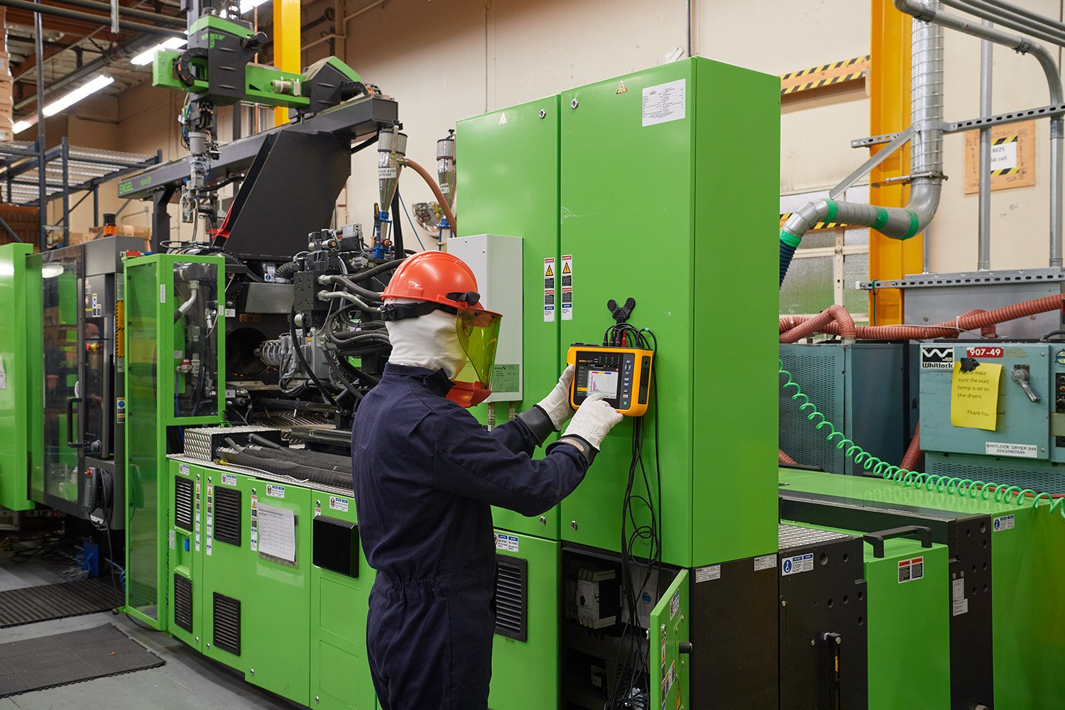
No two days in the field are the same. You need a power quality analyzer that can go where you go and do what you need it to when you get there. With a full range of accessories and built-in features the Fluke 1770 Series makes it easier to get your job done. The slim ergonomic design and integrated hand strap make it easy to hold and the included hanging kit makes it easy to secure your analyzer inside a cabinet. The integrated internal power supply allows the unit to be powered directly from the measured circuit, while a 90-minute battery helps ensure you can still access and review data even when you aren’t connected to a live system.
Quickly and easily transfer data to your PC using the USB C, USB A, Ethernet, Wi-Fi, cellular network support options, depending on your requirements. With an internal GPS module and an optional double insulated antenna extension cable, for amplifying GPS signals indoors, you can easily time sync your data for more accurate troubleshooting and analysis.
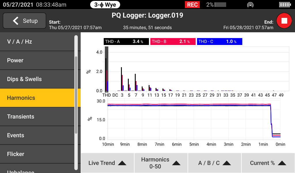
When downloading data from the Fluke 1770 Series Power Quality Analyzers the included Energy Analyze Plus software package can compare measured voltage and current harmonic statistical data to different standards, like EN 50160 or IEEE 519, to determine if they exceed compliance limits. This powerful predictive maintenance feature enables current harmonics to be observed before distortion appears in the voltage allowing you to prevent unexpected failures or non-compliance situations and increase system uptime. With the proliferation of inverter-based loads and power generation, keeping current harmonics in check is becoming increasingly critical to ensure reliable power quality and avoid system downtime.
| Voltage inputs | |
|---|---|
| Number of inputs | 4 inputs, 3 phases and neutral referenced to PE (5 connectors) |
| Measurement category | 1000 V CAT III / 600 V CAT IV |
| Maximum input voltage | 1000 V rms / 1000 V dc (1700 Vpk) |
| Nominal voltage range | Wye and single phase: variable (50 V – 1000 V) Delta: Variable (100 V – 1000 V) IEC 61000-4-30 Class A compliance for the nominal voltages (Vdin) 100 V – 690 V |
| Input impedance | 10 MΩ between P-P and P-N, 5 MΩ between P-PE and N-PE |
| Bandwidth | DC to 30 kHz for PQ measurements, excluding transients |
| Resolution | 24-bit synchronous sampling |
| Sampling frequency | 80 kS/s at 50/60 Hz |
| Scaling | 1:1, variable for use of potential transformers |
| Voltage transients | |
|---|---|
| Measurement range | ±8 kV |
| Sampling rate | 1775: 1 MS/s 1777: 1 MS/s, 20 MS/s |
| Bandwidth | DC to 1 MHz |
| Trigger | Adjustable trigger level. Triggers on high-frequency components > 1.5 kHz |
| Resolution | 14-bit synchronous sampling |
| Current inputs | ||
|---|---|---|
| Number of inputs | 4 inputs 3 phases and Neutral, range selected automatically to attached sensor | |
| Range | AC | 1 A to 1500 A with i17XX-FLEX1500 12 1 A to 1500 A with i17XX-FLEX1500 24 3 A to 3000 A with i17XX-FLEX3000 24 6 A to 6000 A with i17XX-FLEX6000 36 40 mA to 40 A with clamp i40s-EL 4 A to 400 A with clamp i400s-EL |
| DC | 20 A to 2000 A with 80i-2010-EL clamp | |
| Bandwidth | DC to 30 kHz | |
| Resolution | 24-bit synchronous sampling | |
| Sampling frequency | 80 kS/s at 50/60 Hz | |
| Scaling | 1:1, variable | |
| Input voltage | Clamp: 50 mV / 500 mV rms; CF 2.8 Rogowski Coil: 15 mV / 150 mV rms at 50 Hz, 18 mV / 180 mV rms at 60 Hz; CF 4 all at nominal probe range |
|
| Input impedance | 11 kΩ | |
| Aux inputs | |
|---|---|
| Wired connection with 17XX-AUX adapter | |
| Number of inputs | 2 |
| Input range | Direct: 0 V dc to ± 10 V dc 0 V to 1000 V dc |
| Input impedance | Direct: 2.92 MΩ |
| Scale factor | Format: mx + b (gain and offset) user configurable |
| Displayed units | User configurable (up to 8 characters, for example °C, psi, or m/s) |
| Data acquisition voltage and current | |
|---|---|
| Input mains frequency | DC, 50/60 Hz 15 % (42.5 Hz … 57.5 Hz, 51 Hz … 69 Hz) |
| Topologies | 1-φ, 1-φ IT, Split phase, 3-φ delta, 3-φ wye IT, 3-φ Aron/Blondel (2 element delta), 3-φ delta open leg, 3-φ high leg delta |
| Data storage | Fluke 1773/1775: 8 GB internal (expandable with microSD card) Fluke 1777: 32 GB microSD card (installed) |
| Memory size | Typical 10 logging sessions of 8 weeks with 1-minute intervals and 100 events. The number of possible logging sessions and logging period depends on user requirements |
| Real time accuracy | Internal: 3 ppm (0.26 s per day, 8 s per month) NTP (internet time): Depending on internet latency, typical < 0.1 s absolute to UTC GPS: < 1 ms absolute to UTC |
| Trend interval | |
|---|---|
| Measured parameter | See operator manual |
| Trend interval | User selectable: 1 sec, 3 sec, 5 sec, 10 sec, 30 sec, 1 min, 5 min, 10 min, 15 min, 30 min |
| Averaging interval min/max values | Voltage, Current: ½ cycle RMS (20 ms at 50 Hz, 16.7 ms at 60 Hz) Aux, Power: 200 ms |
| Total harmonic distortion | THD for voltage and current is calculated on 50 harmonics |
| Power quality measurements | ||
|---|---|---|
| Measured parameter | See operator manual | |
| Harmonics | h0 … h50 % fund and RMS for voltage, current and power Phase angles for voltage and current up to h11 |
|
| Interharmonics | ih0… ih50 % fund and RMS for voltage and current |
|
| Supraharmonics | 2–9 kHz with 200 Hz bins 9–30 khz with 2 kHz bins RMS for voltage and current |
|
| Harmonics measurement method | Grouped, sub-grouped and single harmonic bins according to IEC 61000-4-7. Method selected automatically based on configured PQ standard or user configurable. |
|
| Total harmonic distortion | Calculated on up to 50 harmonics (depends on selected PQ standard) | |
| Mains signaling | 2 frequencies in the range from 110 Hz to 3000 Hz | |
| Events | Voltage | Dip, swell, interruption, rapid voltage change, mains signaling, waveshape deviation, transients |
| Current | Inrush current | |
| Triggered recordings | Half cycle RMS of voltage and current for 10 s Waveform of voltage and current for 10/12 cycles Mains signaling: 200 ms RMS of mains signaling voltage up to 120 s Transients: Waveform of voltage (Fluke 1777: 1 MS/s or 20 MS/s, 500,000 pts, Fluke 1775: 1 MS/s, 25,000 pts) |
|
| Standard compliance | |
|---|---|
| Power | IEEE 1459 |
| Harmonics | IEC 61000-4-7: Class 1 IEEE 519 (short time and very short time harmonics) |
| Flicker | IEC 61000-4-15 Class F1 |
| Power quality | IEC 61000-4-30 Class A, IEC 62586 PQI-A-PI |
| Power quality compliance | EN 50160 + GOST + NEQUAL + NETCODE + FOL |
| Interfaces | |
|---|---|
| Ethernet | 1 Gbit/s 1000BASE-T |
| USB type A | USB 2.0 high speed for USB flash drives to transfer measurement data, firmware updates and license installation. Max. supply current: 500 mA |
| USB-C | USB 2.0 high speed for data download to PC and calibration (requires USB type A to USB-C or USB-C to USB-C cable) Auxiliary power supply for the Analyzer (requires USB C power adapter PD 2.0 or higher with 9 V 1.8 A support) USB 3.0 super-speed for USB-C flash drives to transfer measurement data, firmware updates and license installation. Max. supply current: 900 mA |
| WiFi/BLE module1 | 802.11 ac 2.4 GHz / 5 GHz, support for concurrent access point and client mode Bluetooth 5.0/BLE Antenna: Internal and external2 |
| LTE/4G module3 | LTE-A Cat 12 Worldwide LTE-A and UMTS/HSPA+ coverage Antenna: External2 |
| GPS | MCX connector to attach a GNSS antenna for GPS/GLONASS2 |
| 1 Not in 177X/BASIC versions 2 Requires 5m extension cable, Fluke p/n 5263915 3 Availability and supported providers vary by country. Check with your local Fluke representative. |
|
| Parameter | Range | Resolution | Intrinsic Accuracy at Reference Conditions % of Reading + % of Full Scale |
|
|---|---|---|---|---|
| Voltage | 1000 V | 0.1 V | 0.1 % of nominal voltage in accordance with IEC 61000-4-30 Class A1,2 ±(0.04 % + 0.004 %)3 |
|
| Voltage dips and swells | - | 0.1 V | 0.2 % of Vnom1,2 | |
| Voltage transients | ±8 kVpk | - | ±5 % +0.25 %) | |
| Voltage harmonics/interharmonics | 100 % | 0.1 % / 0.1 mV | ≥1 % Vnom1: ±2.5 % of rdg. <1 % Vnom1: ±0.025 Vnom |
|
| THD on voltage | 100 % | 0.1 % / 0.1 V | ±(2.5 % + 0.5 %) | |
| Voltage distortions 2-9 kHz | Max 100 V | 0.1 mV | ±(2.5 % + 0.1 V) | |
| Voltage distortions 9-30 kHz | Max 100 V | 0.1 mV | ±(2.5 % + 0.1 V) | |
| Current (Rogowski clamp mode) |
With iFlex 1500 A, i17XX-FLEX1500 24 |
150 A 1500 A |
0.01 % 0.1 A |
±(1 % + 0.02 %) |
| With iFlex 3000 A, i17XX-FLEX3000 24 |
300 A 3000 A |
0.01 A 0.1 A |
±(1 % + 0.03 %) | |
| With iFlex 6000 A, i17XX-FLEX6000 36 |
600 A 6000 A |
0.1 A 1 A |
±(1.5 % + 0.03 %) | |
| With AC clamp 40 A, i40s-EL |
4 A 40 A |
0.001 A 0.01 A |
±(0.7 % + 0.02 %) | |
| With AC clamp 400 A, i400s-EL |
40 A 400 A |
0.01 A 0.1 A |
±(2 % + 0.2 %) ±(0.7 % + 0.1 %) |
|
| With AC/DC clamp 2000 A, 80i-2010s-EL |
200 A 2000 A |
0.01 A 0.1 A |
±(0.8 % + 0.2 %) | |
| Current min/max | 100 % | defined by accessory | x2 of intrinsic accuracy | |
| Current harmonics/interharmonics | 100 % | 0.1 % / 0.01 A | ≥3 % Inom: ±2.5 % of rdg.4 <3 % Inom: ±0.15 % of Inom |
|
| THD on current | 100 % | 0.1 % | ±(2.5 % + 0.5 %) | |
| Frequency | 42.5 Hz … 69 Hz | 0.001 Hz | ±0.01 Hz | |
| Voltage unbalance | 100 % | 0.1 % | ±0.15 % | |
| Current unbalance | 100 % | 0.1 % | ±0.15 % | |
| Flicker Pinst, Pst, Plt | 0 to 20 | 0.01 | 5 % | |
| Mains signaling voltage | Up to 3 kHz 0-15 % of Vnom |
0.1 V / 0.1 % | 1-3 % Vnom: ±0.15 % of Vnom 3-15 % Vnom: ±5 % of rdg. |
|
| AUX input | ±10 V | 0.1 mV | ±(0.2 % + 0.05 %) | |
| 1 Nominal voltage in the range of 100 V to 690 V. Also known as Udin. 2 0 °C to 45 °C: Intrinsic Accuracy x2. Outside of 0 °C to 45 °C: Intrinsic Accuracy x3 3 Only for calibration laboratories 4 With iFlex 1500A, I17XX-FLEX1500 24 |
||||
| Parameter | Direct Input1 | Clamp i40S-EL |
|---|---|---|
| Power range W, VA, var | Clamp: 50 mV / 500 mV Rogowski: 15 mV / 150 mV |
4 A / 40 A |
| Clamp: 50 W / 500 W Rogowski: 15 W / 150 W |
4k W / 40 kW | |
| Max. resolution W, VA, var | 0.1 W | 1 W / 10 W |
| Phase (voltage to current)1 | ±0.2° | ±1° |
| Parameter | iFlex 1500A, I17XX-FLEX1500 24 | iFlex 3000A, I17XX-FLEX3000 | iFlex 6000A, I17XX-FLEX6000 |
|---|---|---|---|
| Power range W, VA, var | 150 A / 1500 A | 300 A / 3000 A | 600 A / 6000 A |
| 150 kW / 1.5 MW | 300 kW / 3 MW | 600 kW / 6 MW | |
| Max. resolution W, VA, var | 0.1 kW / 1kW | 1 kW /10 kW | 1 kW / 10k W |
| Parameter | I17XX-FLEX1500 24 | I17XX-FLEX3000 | I17XX-FLEX6000 | |
|---|---|---|---|---|
| Active power P | PF ≥ 0.99 | 150 A / 1500 A | 300 A / 3000 A | 600/6000 A |
| 1.2 % + 0.005 % | 1.2 % + 0.0075 % | 1.7 % + 0.0075 % | ||
| Active energy Ea | 0.1 ≤ PF < 0.99 | (1.2+√(1-PF2)/(2 PF)) % + 0.005 % | (1.2+√(1-PF2)/(2 PF)) % + 0.0075 % | (1.7+√(1-PF2)/(2 PF)) % + 0.0075 % |
| Apparent power S Apparent energy Eap |
0 ≤ PF ≤ 1 | 1.2 % + 0.005 % | 1.2 % + 0.0075 % | 1.7 % + 0.0075 % |
| Reactive power Q Reactive energy Er |
0 ≤ PF ≤ 1 | 2.5 % of measured apparent power/energy | ||
| Additional uncertainty (% of power high range) |
VP-N > 250 V | 0.02 % | 0.02 % | 0.02 % |
| Phase (voltage to current) | - | 0.28° | 0.28° | 0.28° |
| 1 Nominal voltage in the range of 100 V to 690 V. Also known as Udin.
Reference ConditionsEnvironmental: 23 °C ±5 °C, instrument operating for at least 30 minutes, no external electrical/magnetic field, RH <65 % Input conditions: Cos Φ/PF=1, Sinusoidal signal f=50/60 Hz, power supply 120 V/230 V ±10 %. Current and power specifications: Input voltage >100V Input current > 10 % of current range Primary conductor of clamps or Rogowski coil in center position Temperature coefficient: Add 0.1 x specified accuracy for each degree °C above 28 °C or below 18 °C |
||||
| Key features | |
|---|---|
| Warranty | Analyzer: 2 years (battery not included) Accessories: 1 year (including battery) |
| Calibration cycle | 2 years |
| Size (L X W X HD) | 28.0 cm x 19.0 cm x 6.2 cm (11.0 in x 7.5 in x 2.4 in) |
| Weight | 2.1 kg (4.6 lb) |
| Anti-theft protection | Slot to support Kensington lock |
| Environmental specifications | |
|---|---|
| Operating temperature range | -10 °C to 50 °C |
| Storage temperature range | -20 °C to 60 °C |
| Operating humidity | IEC 60721-3-3: 3K5, modified: -10 °C to 30 °C: ≤95 %, no condensation or ice 35 °C: 70 % 40 °C: 55 % 50 °C: 35 % |
| IP Rating | IEC 60529: IP50 |
| Vibration | IEC 60721-3-3 / 3M2 |
| Power supply | |
|---|---|
| Voltage range | 100 V – 600 V -15 % / +10 % (85 V … 660 V) |
| Power consumption | Max. 40 VA |
| Mains frequency | 50/60 Hz (42.5 Hz … 69 Hz) |
| UPS | Li-Ion battery BP1770 with extended temperature range, customer replaceable On-battery runtime: 1.5 hours |
| Safety | |
|---|---|
| General | IEC 61010-1: Pollution Degree 2 |
| Power supply | Overvoltage Category IV 600 V With Mains Adapter MA-C8: Overvoltage Category II 300 V |
| Measurement | IEC 61010-2-030: CAT IV 600 V, CAT III 1000 V |
| Altitudes 2000 m to 4000 m | Derate to: Power Supply: Category IV 300 V With MA-C8 Adapter: Category II 150 V Measurement: CAT IV 300 V, CAT III 600 V, CAT II 1000 V |