


From R&D Applications to Windings, Coil and Transformer Manufacturing
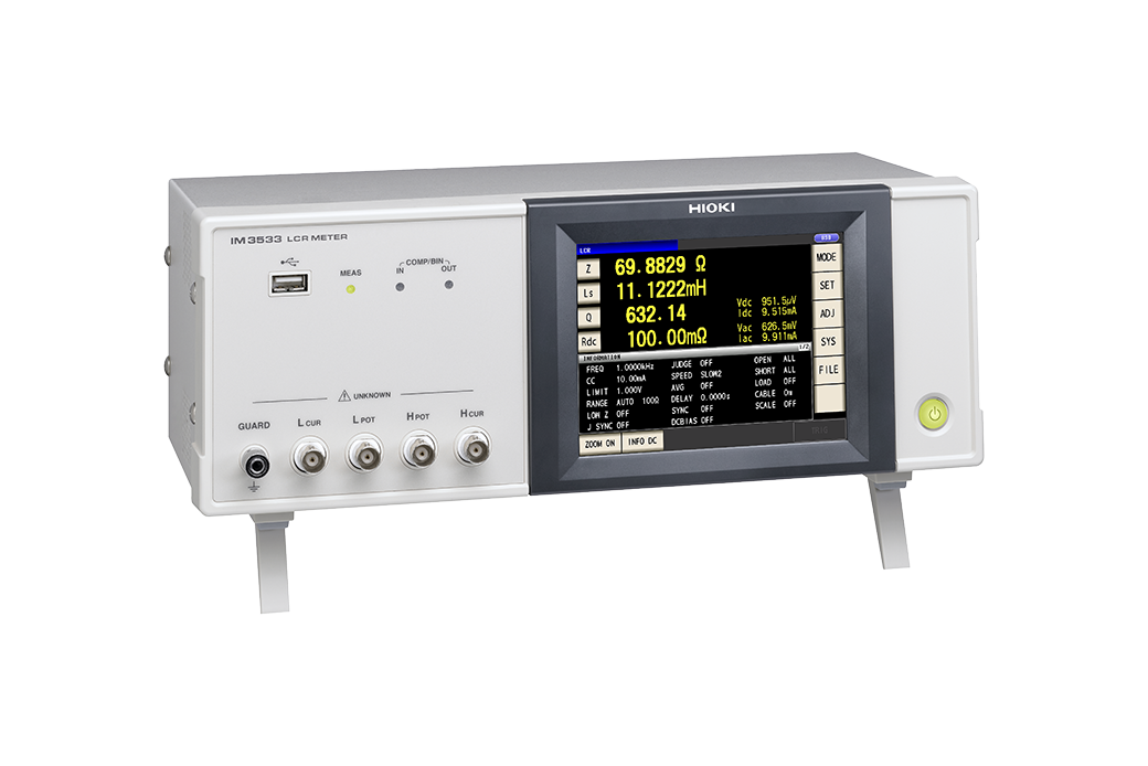
Hioki LCR Meters and Impedance Analyzers range from 1 mHz to 3 GHz devices to suit a wide range of applications in the testing of electronic components. The IM3533 series are Hioki’s first LCR meters to offer turn ratio, mutual inductance and inductance difference measurements of transformers and coils, and are integrated with an internal DC bias to facilitate HDMI compliance testing.
| IM3533 | |
|---|---|
| IM3533-01 | Advanced function model |
The Hioki IM3533 LCR Meter can perform continuous measurement using different capacitor measurement conditions, for example to perform C-D measurement at 120 Hz and ESR measurement at 100 kHz, without stopping to manually change settings.
In transformer and winding measurement, the Hioki IM3533 LCR meter can measure primary-side and secondary-side L values and then calculate and display the turn ratio. This capability eliminates the need to manually calculate this value, as in the conventional approach.
In transformer measurement, the Hioki IM3533 LCR Meter can perform L measurement with a same-phase series connection and again with a reverse-phase series connection, and then calculate and display the mutual inductance. This capability eliminates the need to manually calculate this value, making it more convenient and efficient than the conventional approach.\
The IM3533-01 can perform automatic measurement while sweeping through up to 801 frequencies from a user-specified frequency range or frequency list. Measurement results can be saved on a USB flash drive or computer via the instrument’s interface in order to create lists and graphs of frequency characteristics using the included LCR application software.
| IM3533 | IM3533-01 | |||||
| Measurement modes | LCR (Measurement with single condition), Transformer testing (N, M, ΔL), Continuous testing(Continuous measurement under saved conditions) (LCR mode) | LCR (Measurement with single condition), Transformer testing (N, M, ΔL), Analyzer (sweep testing), Continuous Testing (LCR/Analyzer mode) | ||||
| Measurement parameters | Z, Y, θ, X, G, B, Q, Rdc (DC resistance), Rs (ESR), Rp, Ls, Lp, Cs, Cp, D (tanδ), N, M, ΔL, T | |||||
| Measurement range | 100 mΩ to 100 MΩ, 10 ranges (All parameters defined in terms of Z.) | |||||
| Displayable range | Z, Y, Rs, Rp, Rdc, X, G, B, Ls, Lp, Cs, Cp : ± (0.00000 [unit] to 9.99999G [unit]) Real value display for Z and Y only θ: ± (0.000° to 180.000°), D: ± (0.00000 to 9.99999) Q: ± (0.00 to 99999.9), Δ%: ± (0.0000% to 999.999%), T: -10.0°C to 99.9°C |
|||||
| Basic accuracy | Z : ±0.05% rdg. θ: ±0.03° | |||||
| Measurement frequency | 1 mHz to 200 kHz (5 digits setting resolution, minimum resolution 1 mHz) | |||||
| Measurement signal level | [Normal mode] V mode, CV mode: 5 mV to 5 Vrms, 1 mVrms steps CC mode: 10 μA to 50 mArms, 10 μArms steps [Low impedance high accuracy mode] V mode, CV mode: 5 mV to 2.5 Vrms, 1 mVrms steps CC mode: 10 μA to 100 mArms, 10 μArms steps |
|||||
| Output impedance | Normal mode: 100 Ω, Low impedance high accuracy mode: 25 Ω | |||||
| Display | 5.7-inch touch-screen color TFT, display can be set to ON/OFF | |||||
| Measurement time | 2 ms (1 kHz, FAST, display OFF, representative value) | |||||
| Functions | DC bias measurement, DC resistance temperature compensation (converted reference temperature display), Comparator, BIN measurement (classify function), Panel loading/saving, Memory function | |||||
| Interfaces | EXT I/O (Handler), USB communication (high-speed), USB memory Optional: Choose 1 from RS-232C, GP-IB, or LAN |
|||||
| Power supply | 100 to 240 V AC, 50/60 Hz, 50 VA max | |||||
| Dimensions and mass | 330 mm (12.99 in) W × 119 mm (4.69 in) H × 168 mm (6.61 in) D, 3.1 kg (109.3 oz) | |||||
| Included accessories | Power cord × 1, Instruction manual × 1, CD-R (Includes PC commands and sample software) × 1 | |||||